
 For those of you
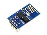
 following me on Twitter, you know that I’ve been on an Internet of Things binge lately. It started off when I finally did something with my Arduino Leonardo after having it for almost a year. My original plan was to find a decent WiFi shield for the Arduino Leonardo but there’s been a recent development of a very interesting, inexpensive products that both has WiFi capabilities and Arduino Sketches can be loaded on it, the ESP8266. And by inexpensive, I mean only $2-3! If you’re impatient and want faster shipping they can be found on Amazon for a few dollars more!
Unfortunately for me, I’m a novice. The biggest problem with being inexperienced is that your problem-solving toolbox starts off pretty empty. Thankfully solving those problems begins to fill up that toolbox, but those first few problems wind up being really difficult to move past. I’m writing this mostly to help move people past the problems that I encountered.
Obstacles I wound up running into a few different obstacles:
- My own cheeky and fun shenanigans.
- I couldn’t get my ESP8266 ESP-01 to talk to my Arduino Leonardo.
- My DROK LM2596 Adjustable Power Supply cooked a couple ESP8266 ESP-01s.
- Nothing but garbage back via my USB-to-Serial adapter.
Shenanigans
My own shenanigans are a minor, yet ever-present challenge whenever I am learning something new. None of my self-inflicted problems are ever incredibly serious, but when you inject one of those into a sequence where you’re unfamiliar it can have very maddening results. Here are a few of those self-inflicted problems that I ran into:
- Forgetting to swap the transmit (TX) and receive (RX) pins between devices: Your ESP8266 can’t talk directly to your computer, so you need to use something like the Arduino or some sort of USB-to-Serial device in order to be able to talk to the ESP8266. Each device has its own transmit and receive pins, which means the ESP8266’s transmit pin needs to be hooked to the other device’s receive pin and the other device’s transmit pin needs to be hooked to the ESP8266’s receive pin. It sounds simple, but when you’re frequently changing things around, it’s easy to get this backwards.
- Neglecting to run power to the CH_PID pin on the ESP8266 ESP-01: Because I bought several ESP8266s ESP-01s, I wound up swapping them in/out frequently, wondering if one device was bad or not. I’d unhook everything and then hook it back up, but I’d very frequently forget to run power to the CH_PID pin and then be dumbfounded as to why it wasn’t powering up.
- A common ground for all devices: At one point, I was using my KEDSUM CP2102 USB-to-Serial adapter and for some reason, I grounded it out on the opposite side of the breadboard as where the ESP8266 and power supply were grounded and the devices just wouldn’t cooperate.
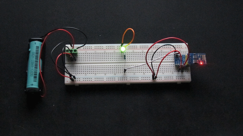
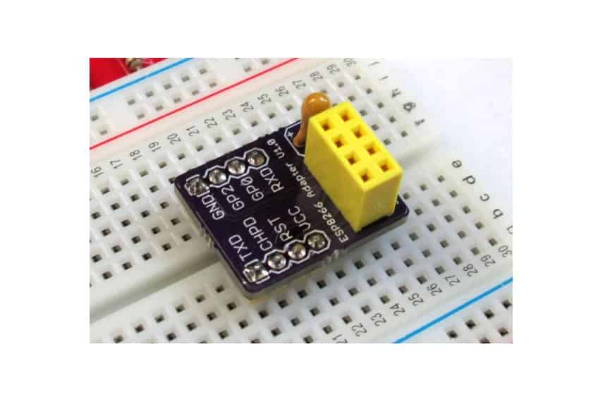
Ultimately, I wound up solving most of these shenanigans by using a breadboard and a breadboard adapter for the ESP-01 along with my ESP8266 ESP-01. Once I had that, I didn’t have any more self-inflicted problems of not hooking the appropriate cables up.
Failure to Communicate
My initial ESP8266 plan was to use the ESP8266 ESP-01, my Arduino Leonardo, and a PIR Sensor to make a little device that I could put by the back door to detect when one of our dogs is by the door wanting to be let out. My first step of that was to get the Arduino Leonardo and ESP8266 ESP-01 conversing with each other. I wrote crude Arduino sketch to run some AT commands and write the response so the Arduino IDE’s serial monitor would display their result. But for some reason, nothing I tried seem to work. The closest I ever got was an “ERROR” response to the basic command “AT”. None of the other ESP8266 AT Commands seemed to be working at all.
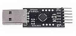 I wound up having to decide if it was my Arduino Sketch, the Leonoardo, or the ESP8266 which was defective. My typical approach is to assume that I’m the most likely source of problems, so I assumed it was the sketch that wasn’t working. I decided to instead of use the Leonardo, I’d just use the KEDSUM CP2102 USB-to-Serial and send AT commands at the ESP8266 manually to see if I got a different result.
ESP8266 Barbecue
Previously, I’d been using the Arduino Leonardo to power the ESP8266 ESP-01, but since I was bypassing that, I’d need to find another power source. I couldn’t use the power available on the KEDSUM CP2102 USB-to-Serial because its default is 5V which, is too much for the ESP8266 ESP-01 which only needs 3.3v of power. Changing the CP2012’s output power was possible, but it was going to require soldering some pins and I didn’t want to do that yet unless I really had to.
 Thankfully, I had purchased a DROK LM2596 Adjustable power supply which could be easily adjusted down to 3.3v. I immediately hooked it up to power the ESP8266 ESP-01 and used the CP2012 adapter to transmit data between my computer and the ESP-01, but for some reason I wasn’t getting any response. The activity LED on ESP-01 never made any indication that data was being transmitted, despite a plethora of AT commands being sent.
At one point, I touched the ESP-01 and found it to be really hot. I asked my friend Pat if that was unusual and his response was “Yeah, they get pretty warm. Even at 3.3 volts!” The next day we planned to nerd out in my kitchen and solve all my ESP8266 problems once and for all. After Pat also failed, to get any kind of response to AT commands he reached down to pick up the ESP-01 and immediately yanked his hand back like he’d been bit. Apparently, my ESP-01 was running a bit warmer than normal!
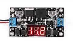
We used a cheap multimeter to check the output voltage from the DROK LM2596 Adjustable power supply to make sure it was operating at the expected voltage and it was. Assuming the ESP-01 was just defective, we swapped it out for another one. When we powered everything back on, I noticed something peculiar on the DROK LM2596’s display and captured a video of it. The display on the LM2596 is a little hard to read, so I left the multimeter hooked up too:
After powering on the DROK LM2596 Adjustable power supply, the output display fell from the voltage of the adapter (12v) down to the voltage the DROK LM2596 was set at (3.3v). Initially, we hoped that this was just a display error, but the multimeter confirmed what we suspected. We found that the initial output voltage was as high as 12v in those first few moments and likely frying the ESP8266 ESP-01! I’m glad we caught that after two ESP-01s!
Garbledy-gook
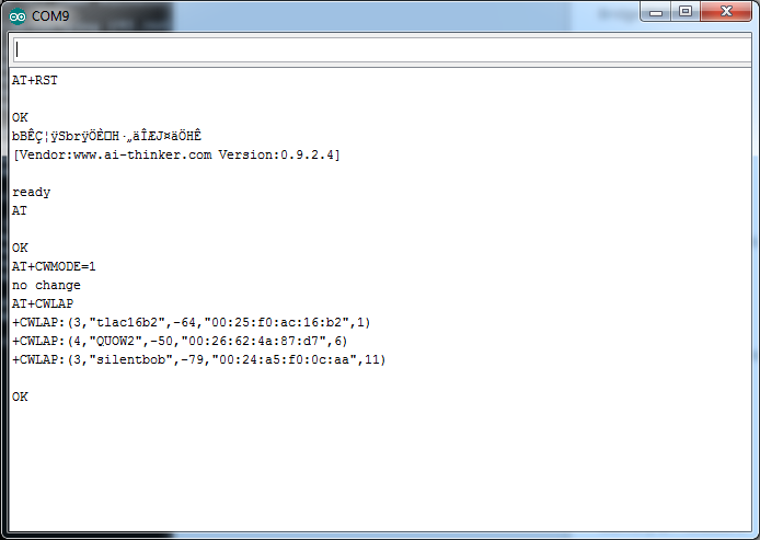
After solving the combustible ESP8266 ESP-01 problem, we still couldn’t get the ESP-01 to respond to the AT commands. Pat’s experience with the ESP-01 was that they communicated either at two different baud rates: 115200 or 57600. Some Googling confirmed Pat’s experience and assumption, but for some reason we’d get garbled output back from the KEDSUM CP2102 USB-to-Serial when we used it to send AT commands. That’s when we decided to try every supported baud rate in the Arduino IDE’s serial monitor. We started at 115200 and worked our way down, eventually landing at 9600 when we got the expected “OK” back from the plain old AT command.
Even then, we weren’t in the clear. We kept trying to run the the AT+CWLAP command, which should list the WiFi access points that the ESP8266 ESP-01 can see, but we kept getting the ERROR response to that command. Ultimately, what we found is that my ESP-01s were all in the Access Point mode and apparently the AT+CWLAP command doesn’t work when it’s in that mode. Sending a AT+CWMODE=1 changed the mode and finally I was getting somewhere with the ESP8266!
All Problems Conquered!
Now that I finally had achieved my goal of having luck with AT commands, I was pretty confident I could use one of the sketches that came with the ESP8266 Arduino IDE add-on package (File > Examples > ESP8266WiFi > WiFiWebServer from inside the Arduino IDE) which toggles the LED based off of hitting a URL being served up by the ESP-01. However, I did run into a momentary wrinkle uploading the sketch; in order to upload a sketch, you have to set the GPIO0 pin to low as it boots up. The ESP-01 firmware uses this to put the ESP-01 into its download mode.
Once I was finished uploading the sketch, I added a resistor and a green LED to run off of GPIO2 on my breadboard. After I powered it on, I was then able to pull up the two URLs (it’s documented in the sketch’s comments) in a browser that turn the LED on and off.
Suggestions
So, here are a few suggestions that I’ve come up with based on what’s gone well and what hasn’t gone so well for me.
- Download [Arduino IDE 1.6.4][ard_download] or later: They improved the IDE to make the management of boards like the various ESP8266s easier in version 1.6.4.
- Follow the _Installing with Boards Manager_ directions at the [ESP8266 Arduino Github][esp8266_gh] page: These steps will install everything that you need in order to start developing sketches for the ESP8266.
- Purchase some extra [ESP8266 ESP-01s][esp8266_amz], especially if you buy at the $2-3 price point: They’re cheap enough to buy a handful of them and have some spares in case something bad happens. It’s a luxury to have some extra lying around when you need to troubleshoot why something is not working the way it should.
- Buy some [breadboard adapters for your ESP8266 ESP-01][bb_esp01]: I can’t recommend these enough, they really helped cut out some of my self-inflicted nonsense.
- Use your USB-to-Serial adapter and run some AT commands first to validate that you've got the hardware wired up correctly:
- Build a "download station" using a [mini-breadboard][minibb], an [ESP8266 ESP01 breadboard adapter][bb_esp01], your USB-to-Serial adapter, and a 3.3v power source: There aren’t very many GPIO pins on the ESP-01. If you want to do something more complicated than light up a single LED, then you’ll need to use the GPIO0 pin, TX pin and RX pin, but all of those are used in the transmission of sketches. Having a download station like this will save you some frustration of constantly re-wiring your device before/after each sketch download.
Do you have experience with any of the ESP8266 boards? What other tips am I overlooking that would help a newbie like myself get started? Please share your tips in the blog’s comments and I’ll keep this list up-to-date with the best tips.
What’s Next?
My first thought for a little ESP-01 device is pretty simple. I’d like to make something that monitors my blog. Every few minutes it’ll do an HTTP GET of something that’s up on my blog. If the result is positive, it’ll light up a green LED. If the result is negative, it’ll light up a red LED. After that little device is done, hopefully I’m going to start using the ESP8266 boards and Arduino sketches to start building out some interesting home automation tools.